Ground penetrating radar (Georadar)
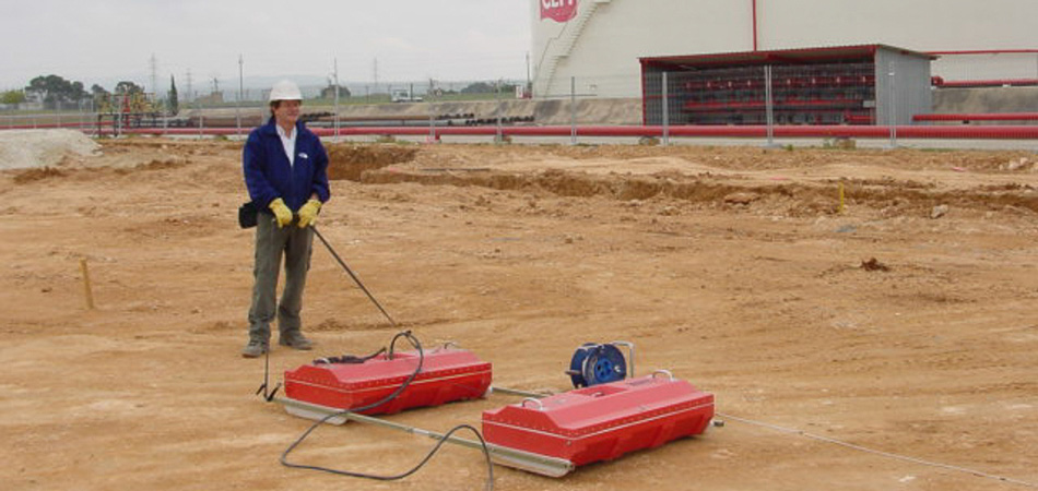
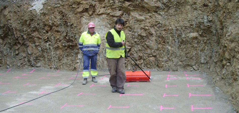

Georadar is a geophysical technique indicated for applications that require a high vertical resolution; for the detection of subsurface structures with length scales of 1.0 m or less. Our geophysical services of georadar are widely used in auscultation.
The georadar uses electromagnetic pulses of very short duration, 1-60 nanoseconds (ns = 10-9 seconds), in the band of VHF / UHF (20-1000 MHz), that are repeated with a frequency of 50 KHz.
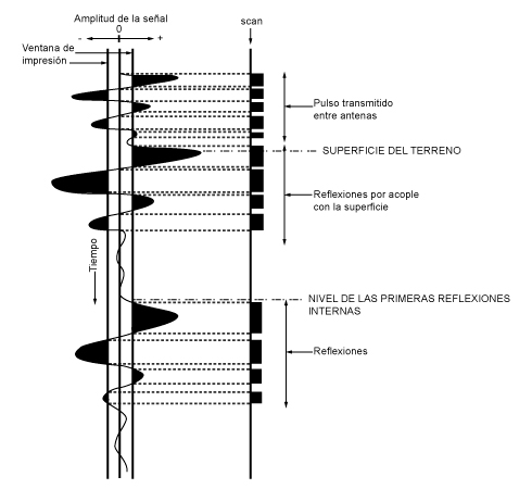
These impulses are grouped into packets of waves composed of 1,000-15,000 of them. When, by means of the transmitting antenna, these impulses are generated, these, in their trajectory through the subsoil, can be found with a change of geological stratum or cultural, hollow, objects, humidities or water tables, etc .; In short, what they detect is a change in the electrical properties (dielectric constant) of the media in which they propagate. This causes some of the energy to be reflected and collected by the receiving antenna, while the remainder continues its path through the interior of the subsurface (see Figure 1).
The receiving antenna incorporates an electronic circuit, "demodulator", connected to the electronic circuit of amplification and reception. Once the reflections reach it, this circuit converts the electromagnetic pulse of high frequency in another of band of audiofrecuencia that is sent through a coaxial cable highly shielded to the central unit, where the signal is reconstructed, processed And stored.
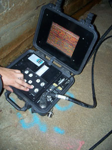
The central unit incorporates a system of mass storage of data and a screen of visualization in real time where reproduces the signal that arrives to him.

Each impulse that is received materializes in a trace, so that when moving the antenna on the surface of the ground can obtain a continuous record that reflects the stratigraphy and / or the existence of anomalies in the subsoil.
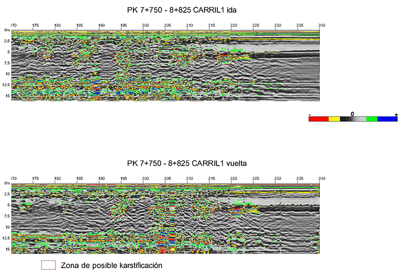
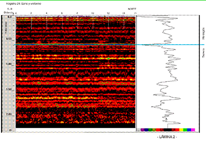
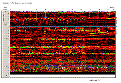
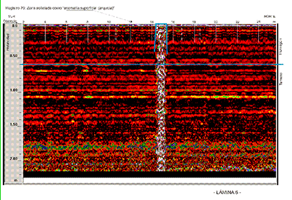
Figure 2 schematizes the implementation of the cited process. When the signal is received in the control console, it applies a window of amplitudes, whose size and color decides the operator. Amplitudes that exceed the set window appear on the screen. The result is a register (radargram), where the axis of abscissa corresponds to the displacement of the antenna on the ground, or lateral movement, and the axis of ordinates reflects the time invested by the pulse in crossing the antenna-reflector-antenna path, also called double time of reflection, whose unity is the nanosecond.
If the velocity of propagation of the investigated medium or its relative dielectric constant is determined, the vertical time scale can be converted to depth (meters).
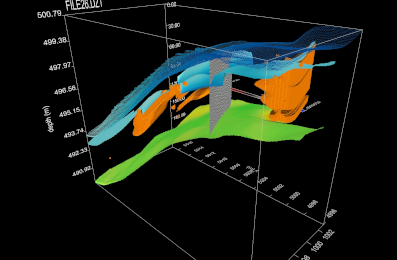
Resolution of studies in 3D

GPR applications
Its fields of application are multiple and varied. In general it is used for the detailed detection of all kinds of materials with sufficient contrast of Dielectric Constant with its surroundings. For example:
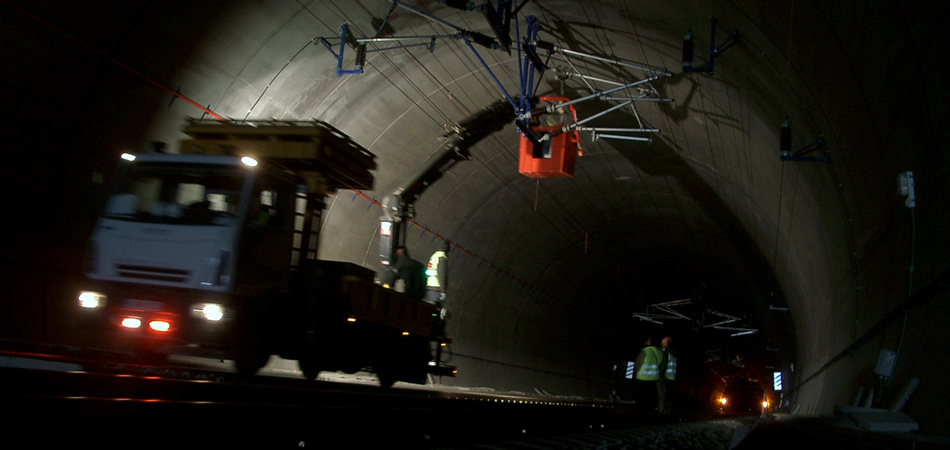
Auscultation of tunnels, pavements and walls, detection of cavities, study of contaminations, location of archaeological sites and buried objects, study of surface geological formations, etc.
In general the depth of investigation will not exceed 30-40 m for studies in very resistive formations
Examples of georadar projects
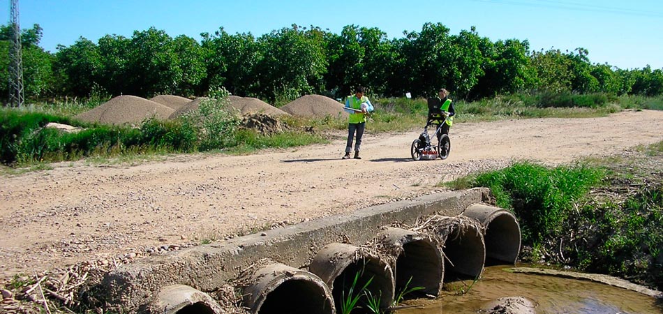
Use of georadar in auscultation of the subsoil of a road
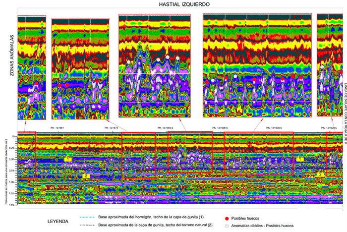
Auscultation of a tunnel by georadar
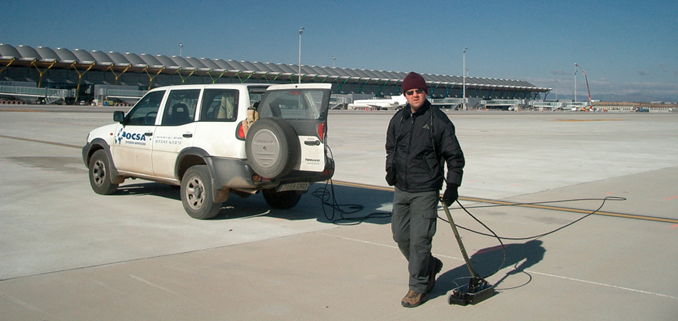
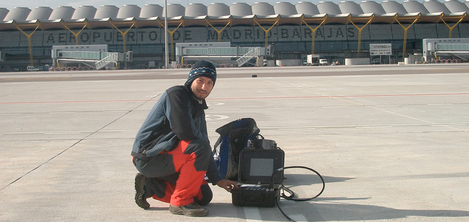
Investigation with georadar of the rolling ground of an airport
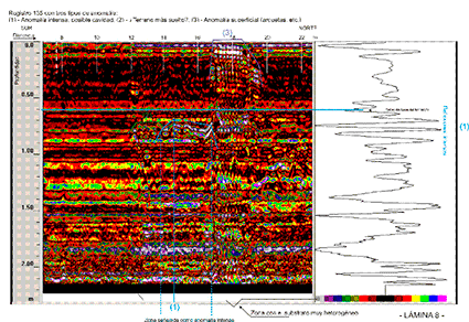
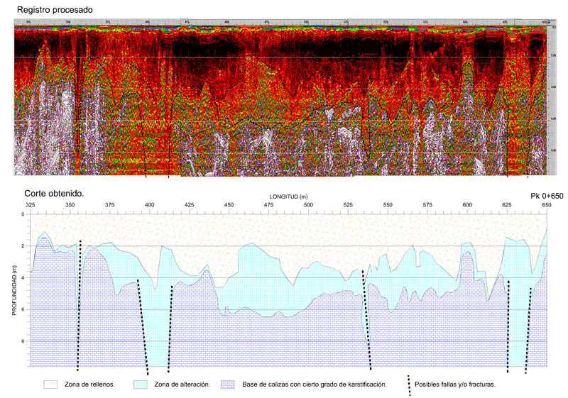
Detection of karstified zones in limestones with georadar